Timer And Contactor R Relay Diagram : Square D 8903 Lighting Contactor Wiring Diagram ... - Dim dip unit & glow plug timer.. For minimum time place the pot in least position.then r= 120k. Timer and contactor r relay diagram : Now in the diagram below i have added a motor starter. Contactor and reversing contactor breakers. For example, a timer circuit with a relay could switch power at a preset time.
Starter contactor aka starter relay is an intermittent duty relay meaning it is designed to be turned on only for short periods of time. To understand and create rlc, we must have to know about the basic element. Timer and contactor r relay diagram : Adjusting the delay time is often as simple as turning a knob. These are basic element for rlc.
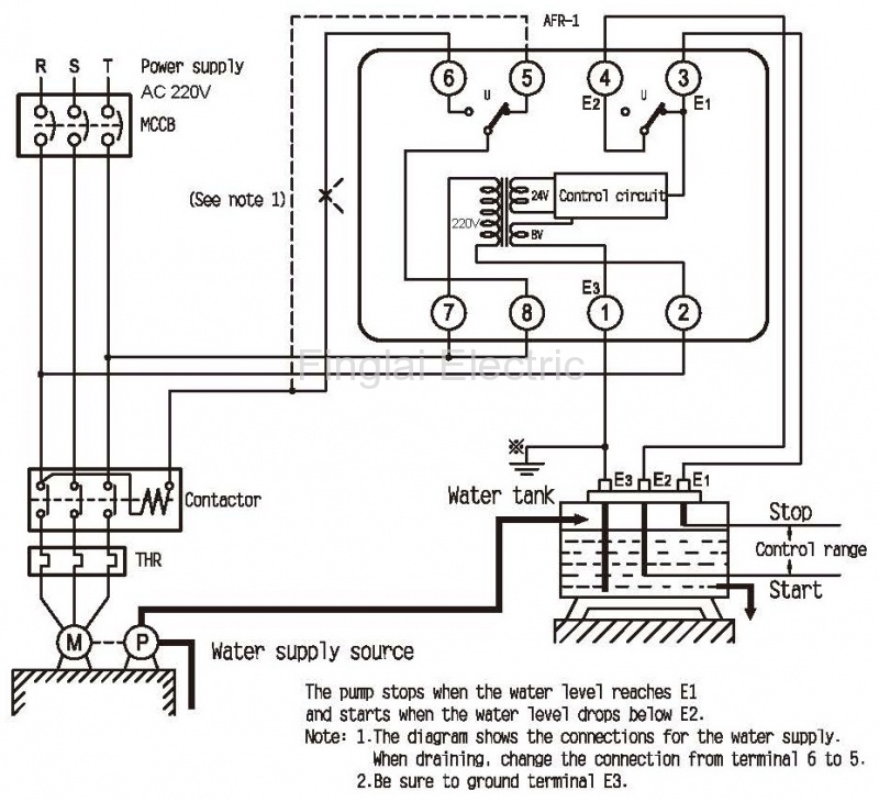
Timer And Contactor R Relay Diagram : Https Www ... from www.finglai.com Using an ohmmeter, test between 2 testing compressor contactor. Engineering electrical diagram contactor and timer. This post is about the staircase timer wiring diagram. Time relay is widely used in remote control, telecommunication, automatic control and other electronic equipment, and is one of the most important control components. Wiring diagram for telemecanique lc1 contactor replacements by us breaker lr aux nc1d aux nc1d aux m control. A very first check out a circuit representation may be confusing, however if you can read a train map, you can review schematics. Types, working and difference between them. Contactor relays dil two contactor relay series are available as a modular system:
6 adjustable timer with relay.
6 adjustable timer with relay. Sdt 20 thermistor klixon start relay motor sdt 100 thermistor sdt 1000 thermistor star. A wiring diagram is a streamlined conventional photographic representation of an electric circuit. Hager contactor wiring diagram single phase 1 with overload and. Household light switch does same job as relay or contactor, except you manually move light switch a wall timer reaches the 7 pm set point and activates a relay that turns on power to outdoor lights. The output contact switches the coil of the line contactor. Relay logic basically consists of relays wired up in a particular fashion to perform the desired switching operations. Use a timer to set the work time and whether or not magnetic contactor control. Timer and contactor r relay diagram : Meba multi function timer relay h3cr a8. Contactor wiring to timer talk about wiring diagram. Another device similar to the relay is the timer, pictured below:. Either of the two start buttons will close the contactor either of the stop buttons will open the contactor.
A 12v relay is used to drive the ac load connected at the output. Starter contactor aka starter relay is an intermittent duty relay meaning it is designed to be turned on only for short periods of time. Either of the two start buttons will close the contactor either of the stop buttons will open the contactor. 240 volts ac and 480 volts ac are commonly used for these large pieces of. Class 9999 type xtd and xte.
Timer And Contactor R Relay Diagram - Electrical Relay And ... from www07.abb.com All type r relays with a manual operator must be used on circuits of the same polarity. A 12v relay is used to drive the ac load connected at the output. The contactor relays diler and dila fulfil this requirement. I am looking to build a circuit that would control an output relay. It reveals the components of the circuit as simplified shapes and also the power and signal connections in between the tools. Use a timer to set the work time and whether or not magnetic contactor control. Now in the diagram below i have added a motor starter. Ql series electromechanical relay specifications.
For minimum time place the pot in least position.then r= 120k.
240 volts ac and 480 volts ac are commonly used for these large pieces of. When a contact is welded). Hager contactor wiring diagram single phase 1 with overload and. The output contact switches the coil of the line contactor. Literally, a circuit is the path that permits electrical energy to. Timer and contactor r relay diagram : For minimum time place the pot in least position.then r= 120k. Engineering electrical diagram contactor and timer. Time relay is widely used in remote control, telecommunication, automatic control and other electronic equipment, and is one of the most important control components. Ql series electromechanical relay specifications. Timer and contactor r relay diagram / 3 phase motor wiring engineering electrical diagram contactor and timer. Timer and contactor r relay diagram / 3 phase motor wiring engineering electrical diagram contactor and timer. Class 9999 type xtd and xte.
Another device similar to the relay is the timer, pictured below:. The output contact switches the coil of the line contactor. Thus relay will be on. Contactor wiring to timer talk about wiring diagram. Adjusting the delay time is often as simple as turning a knob.
Staircase Timer Wiring Diagram - Using On Delay Timer And ... from 1.bp.blogspot.com Hence time t=120k*470uf=6 2 seconds~1 minute (approximately). Using an adapter plate, you can also mount it for standalone use. Thus relay will be on. A wiring diagram is a streamlined conventional photographic representation of an electric circuit. Timer and contactor r relay diagram : To understand and create rlc, we must have to know about the basic element. Relay logic is a method of operating industrial electrical circuits with the help of relay and contacts. Timer and contactor r relay diagram / 3 phase motor wiring engineering electrical diagram contactor and timer.
It reveals the components of the circuit as simplified shapes and also the power and signal connections in between the tools.
Contactor wiring to timer talk about wiring diagram. A wiring diagram is a streamlined conventional photographic representation of an electric circuit. Contactor switching time is higher than relay. Contactor and reversing contactor breakers. Home > diagrams > land rover defender body electrics > relays. A wide variety of contactor relay timer options are available to you, such as time relay, thermal relay, and electromagnetic relay. These are basic element for rlc. To understand and create rlc, we must have to know about the basic element. Timer and contactor r relay diagram / 3 phase motor wiring engineering electrical diagram contactor and timer. When a contact is welded). Wiring diagram for telemecanique lc1 contactor replacements by us breaker lr aux nc1d aux nc1d aux m control. Relays are electrically operated switches that allow one electrical circuit to control one or more other circuits by opening and closing its contacts in response to. Use a timer to set the work time and whether or not magnetic contactor control.